filmov
tv
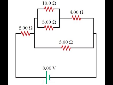
for the circuit shown in the figure calculate the following
0:09:45
For the circuit shown in the figure, calculate (a) the current in the 2.00-Ω resistor and (b) the po
0:04:10
Series Circuit calculation- Electricity
0:02:11
See the electrical circuit shown in this figure. Which of the following equations
0:04:32
Using Kirchoff's laws in the electrical net work shown in figure, calculate the values of
0:09:36
Nodal Analysis : Calculate the node voltages in the circuit shown in Fig
0:03:02
See the electrical circuit shown in this figure. Which of the following equations is a correct equa
0:02:50
Transfer Function (Solved Problem 1)
0:12:15
Consider the circuit shown in the figure below
0:02:18
In the circuit shown 5 resistances are connected. The equivalent resistance between the two ...
0:11:28
In the circuit of the figure below determine the current
0:02:42
Kirchhoff’s Laws : Calculate v and ix in the circuit of Fig
0:05:04
In the circuit shown in figure. Calculate the current in each resistance. The internal resistnaces
0:00:52
In the circuit shown below, the reading of the voltmeter \( V \) is [MP PET 2003] (a) \( 12 \mat...
0:04:54
Nodal Analysis with supernode : For the circuit shown in Fig 3 9, find the node voltages
0:07:24
[Solved]- Numerical for a BJT (Ib, Ic, Vce & Vcb =? )
0:03:20
Find the output of the op amp circuit shown in Fig. Calculate the current through the feedback resis
0:07:46
Thevenin's theorem Solved Example | Electric Circuits | Network Analysis | Network Theory
0:09:50
Find v(t) and i(t) in the circuit shown in Fig. | Sinusoids and Phasors
0:00:11
IIT Bombay CSE 😍 #shorts #iit #iitbombay
0:06:50
In the circuits shown below, the readings of the voltmeter and the ammeter will be:NEET 2019 Physics
0:02:46
In the circuit shown below: The potential difference across the 3Ω resistor is: a) 1/9 V b) 1/2V c)
0:12:36
Finding current & voltage in a circuit- Solved example (Hindi)
0:10:52
Resistors In Series and Parallel Circuits - Keeping It Simple!
0:11:59
(a) the current in the 20.0- resistor and (b) the potential difference between points a and b.
Вперёд
visit shbcf.ru
 0:09:45
 0:04:10
 0:02:11
 0:04:32
 0:09:36
 0:03:02
 0:02:50
 0:12:15
 0:02:18
 0:11:28
 0:02:42
 0:05:04
 0:00:52
 0:04:54
![[Solved]- Numerical for](https://i.ytimg.com/vi/gu_FYvL5zc4/hqdefault.jpg) 0:07:24
0:07:24
 0:03:20
 0:07:46
 0:09:50
 0:00:11
 0:06:50
 0:02:46
 0:12:36
 0:10:52
 0:11:59